|
      
| |
Phase-Change Media for CSP Thermal Energy Storage
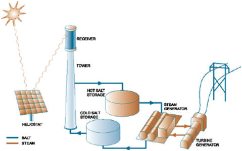
Conventional dual-tank storage system in a
concentrating solar tower system; from (EnergyBlog 2005).
Sensible heat storage systems, as opposed to latent heat storage
(i.e., PCMs), depend solely on the thermal conductivity and heat capacity of the
storage media. The vast majority of TES systems currently in use employ sensible
heat storage (Goswami, Kreith et al. 2000).
In addition to the distinction between sensible and latent heat storage systems,
we can also draw a distinction between active and passive systems. Simply put,
active systems require mechanical steps in addition to the pumping of heat
transfer fluid (HTF) to implement the storage scheme; passive systems, on the
other hand, merely require pumping HTF through stationary storage media
(sensible or latent).
A great many different sensible storage systems have been conceived. These
include (Medrano, Gil et al. 2010): steam accumulation; thermoclines; dual-tank
systems; and passive concrete.
These methodologies are discussed in more detail below.
Steam Accumulation
The idea behind steam accumulation is a simple one: use the same process fluid
used in the power block (water / steam) to store excess thermal energy. In fact,
this technology has been refined through extensive prior use in fossil fuel
plants. The general design of such a thermal storage system, in tandem with a
solar tower plant, is illustrated below (Steinmann and Eck 2006).
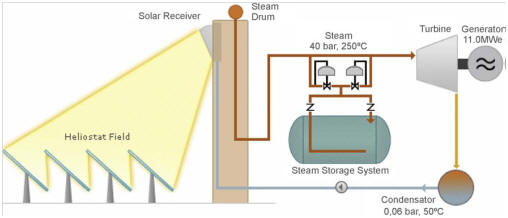
Solar tower plant with direct steam generation
storage; from (Steinmann and Eck 2006).
Basically, excess steam is directed to a storage tank where it
is pressurized to saturated liquid water. When solar insolation declines, for
whatever reason, the outlet of the tank is opened, allowing the expansion of the
liquid water into pressurized steam, which can drive the turbine in lieu of
steam obtained directly from the solar heating. This arrangement makes for ease
of compatibility with conventional fossil fuel sources, which may augment the
supply of steam when solar energy and stored thermal energy are unavailable.
Also, steam accumulation may be paired with other storage media, including PCMs,
if a secondary storage system is needed to provide superheated steam for more
efficient turbine operation (Medrano, Gil et al. 2010).
Thermoclines
In the context of thermal energy storage, thermoclines are simply large tanks of
a particular heat transfer medium, such as concrete, through which the HTF
flows. To maintain the temperature gradient across the tank, the HTF is
initially drawn out of the bottom of the tank, run through the solar field, and
returned through the top at higher temperature. When the tank needs to
discharge, the process is reversed, with hot HTF flowing from the top of the
tank, through the power block, and then returning at lower temperature to the
bottom of the tank. A basic schematic for the thermocline utilized at the 1MW
Saguaro plant in Arizona is shown below (Kolb 2006).
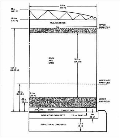
Design of thermocline storage tank; from (Kolb
2006).
Dual-Tank Storage Systems
Dual tank storage systems are designed to keep hot and cold HTFs separate from
one another. A sample system layout is illustrated at the top of this
page. The basic idea is that one tank will hold cold HTF, siphoned from the
power block effluent, and the other tank will hold hot HTF, which is taken
directly from the solar field. The inherent benefit behind this design is the
separation, and therefore improved thermal control, of the hot and cold fluids
(Herrmann and Kearney 2002). Indeed, the Solar Two plant in California
demonstrated 97% round-trip storage conversion efficiencies with this
arrangement, using molten salts for the HTF (Medrano, Gil et al. 2010). The
downside, of course, is the need for additional tanks, piping, and pumps, which
would not otherwise be required of a storage system with a single tank (e.g.,
thermocline). Also, as was the case with Solar Two, immersion heaters may be
required to maintain appropriate HTF operating temperatures, in addition to the
large amount of necessary insulation materials (Medrano, Gil et al. 2010).
Passive Concrete
In this storage system, the thermal energy is stored passively--that is, the
systems heat exchanger is simply embedded within concrete blocks that absorb and
alternately release heat, as shown in the picture from Plataforma Solar de
Almeira, below (Medrano, Gil et al. 2010). The advantages of this system are
clear: simplicity and low cost. Concrete is among the cheapest materials to
employ for thermal storage. And yet, it is has a surprisingly high volumetric
heat capacity: according to a study dated 2002, reinforced concrete possesses
80% of the heat capacity of sodium nitrate PCM, and it is just one quarter the
cost on a thermal kWh basis (Herrmann and Kearney 2002).
Such systems are not without their drawbacks, however. Given the rigid nature of
the design, less control and flexibility is allowed. Also, in some cases,
repeated thermal cycling has led to the development and propagation of cracks in
the concrete matrix, which can compromise thermal storage efficacy.
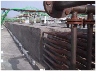
High temperature passive concrete storage
system at Plataforma de Almeira; from (Medrano, Gil et al. 2010).
Conclusion
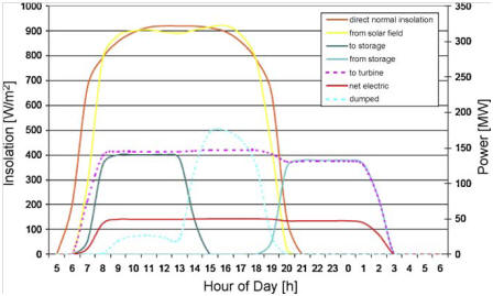
Power distribution curves for the AndaSol I
solar power plant (Medrano, Gil et al. 2010).
We can see from the picture above the true value of effective
thermal storage: use of appropriately designed TES systems can allow for
consistent turbine operation over much of the day. But what of PCM storage
schemes? With all the approaches discussed above, what additional value do PCMs
bring to this problem? We discuss that in the next section.
|